History
In 1845, the German engineer Rudolf Eduard Schinz discovered the principle of pressure measurement by means of a Bourdon tube rather by chance when he tried to repair deformed tubes by applying internal pressure. Rudolf Eduard Schinz recognized that pressurized tubes repeatedly showed the same change in shape. Because of the amazingly high repeatability of this effect, he developed the first Bourdon tube pressure gauge. The Bourdon tube had an elliptical cross-section. The first Bourdon tube pressure gauges were used to measure steam pressure in locomotives.
The instrument maker Eugène Bourdon from Paris patented this measuring principle in 1848, which is why the Bourdon tube is still called the Bourdon tube today.
Structure and mode of action
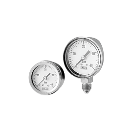
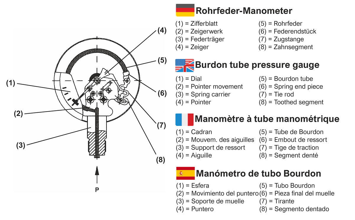
Bourdon tube pressure gauges have a Bourdon tube as a measuring element, which is either circular or helical in shape, depending on the pressure to be measured. The Bourdon tube always has an oval cross-section, it must not have a circular shape, otherwise the desired effect will not occur. By the tube cross-section, the tube wall thickness and the geometry of the cross-section, as well as the material used determine the pressure measuring range.
When the pressure inside the Bourdon tube becomes greater than on the outside, the material strives to change the oval cross-section in the direction of a circular shape. In this process, the bent Bourdon tube bends up slightly, and the free end performs a linear movement. The spring travel is between 2 and 6 mm, depending on the Bourdon tube and the measuring range. This spring travel is transmitted to a pointer mechanism via a tie rod. The pointer mechanism converts the linear movement into a rotary movement. The rotary movement is displayed on the scale (dial) via the deflection of the manometer pointer.
Due to the design and also desired, the relative overpressure inside the Bourdon tube is always measured compared with the pressure applied outside. Thus, from a physical point of view, this measuring principle is always a differential pressure measurement between the ambient air pressure and the system pressure (pressure source).
Special features
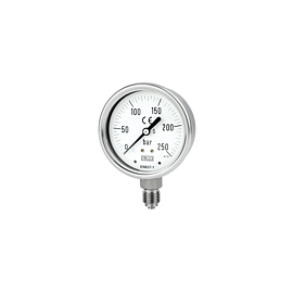
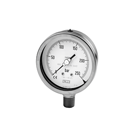
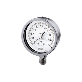
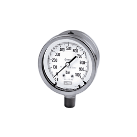
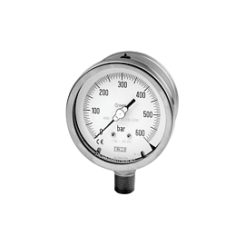
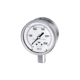
Bourdon tube pressure gauges can be used for indication ranges between 0.6 bar (600 mbar) and 1000 bar. For pressures up to 60 bar a bourdon tube in circular form (angle approx. 245°C) is used, for higher pressures a bourdon tube in helical form with 2 1/2 turns. For small pressure measuring ranges the Bourdon tubes have an olive-shaped profile, for larger pressure measuring ranges a simple flattening. Higher pressures can be measured with stainless steel Bourdon tube pressure gauges.
Pointer movements
Pointer mechanisms are used in different transmission ratios, depending on the spring travel of the Bourdon tubes in relation to the measuring range. They are robust, wear-resistant and low-friction and must also be able to operate independently of position. They are high-precision precision mechanical components. The bearing seats of the segment shafts and the pointer axes are made of nickel silver and/or brass or stainless steel and have an excellent surface finish. This ensures silky-smooth running of the pointer, minimizes wear and thus increases the service life of the Bourdon tube pressure gauge.
Housing
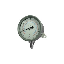
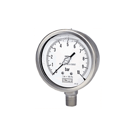
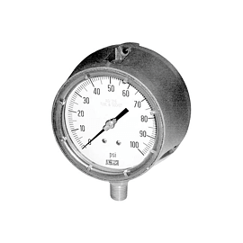
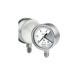
The housing of a Bourdon tube pressure gauge protects all internal parts from mechanical effects and contamination. There are housings made of sheet steel, plastic or stainless steel. If vibrations in the system or larger pressure pulsations caused by the measured medium can occur during pressure measurement, the housing should be filled with a damping liquid (usually glycerine) ("glycerine pressure gauge"). This prevents the bourdon tube from oscillating, stabilizes the pointer indication and protects the pointer mechanism from wear.
Application
Bourdon tube pressure gauges are the most commonly used pressure measuring devices. They are inexpensive, very stable in the long term and easy to handle. They are suitable for all gaseous and low-viscosity media that do not attack the materials of the wetted parts and do not crystallize or are highly viscous.
Measuring ranges:
Relative pressure ranges 0...0.6 bar to 0...1000 bar, vacuum ranges to -1...0 bar as well as manovacuum ranges.
Higher measuring ranges: see stainless steel Bourdon tube pressure gauges
Case diameters:
Nominal sizes (DN) 40, 50, 63, 72x72, 80, 100, 160 and 250 mm.
Accuracies: Cl. 1.0, Cl. 1.6 or Cl. 2.5
Areas of application
- Hydraulicx
- Mechanical and plant engineering
- Energy supply
- Pump systems
- Compressors
- Chemical and petrochemical industry
- Food industry
- Water treatment
Application limits
Bourdon tube pressure gauges are not suitable for pressure media which attack the material of the wetted parts, crystallize or are highly viscous. Without liquid damping in the housing, Bourdon tube pressure gauges are very sensitive to vibrations and dynamic loads. A process connection with a flange is not technically feasible. They are only safe against overpressure to a limited extent. Measuring ranges below 600 mbar are not possible.
Note on the process connection
The G 1/2 B thread (1/2" BSP pipe thread) is permissible for pressures up to a maximum of 1600 bar. Special high pressure connection threads are available for higher pressure measuring ranges: [PDF data sheet high pressure connection thread].