History
The diaphragm pressure gauge was invented by the German manufacturer Bernhard Schäffer, who received a Prussian patent for it in 1849. The diaphragm pressure gauge is the result of the development of a robust pressure gauge for use in steam locomotives. The great resistance of this type of manometer to vibrations and shocks replaced the (toxic) mercury U-tube manometers previously used.
Later, Bernhard Schäfer, together with his brother-in-law Christian Friedrich Budenberg, founded the company "Schäffer & Budenberg" in Magdeburg, a name that is still well known in professional circles today.
Structure and mode of action
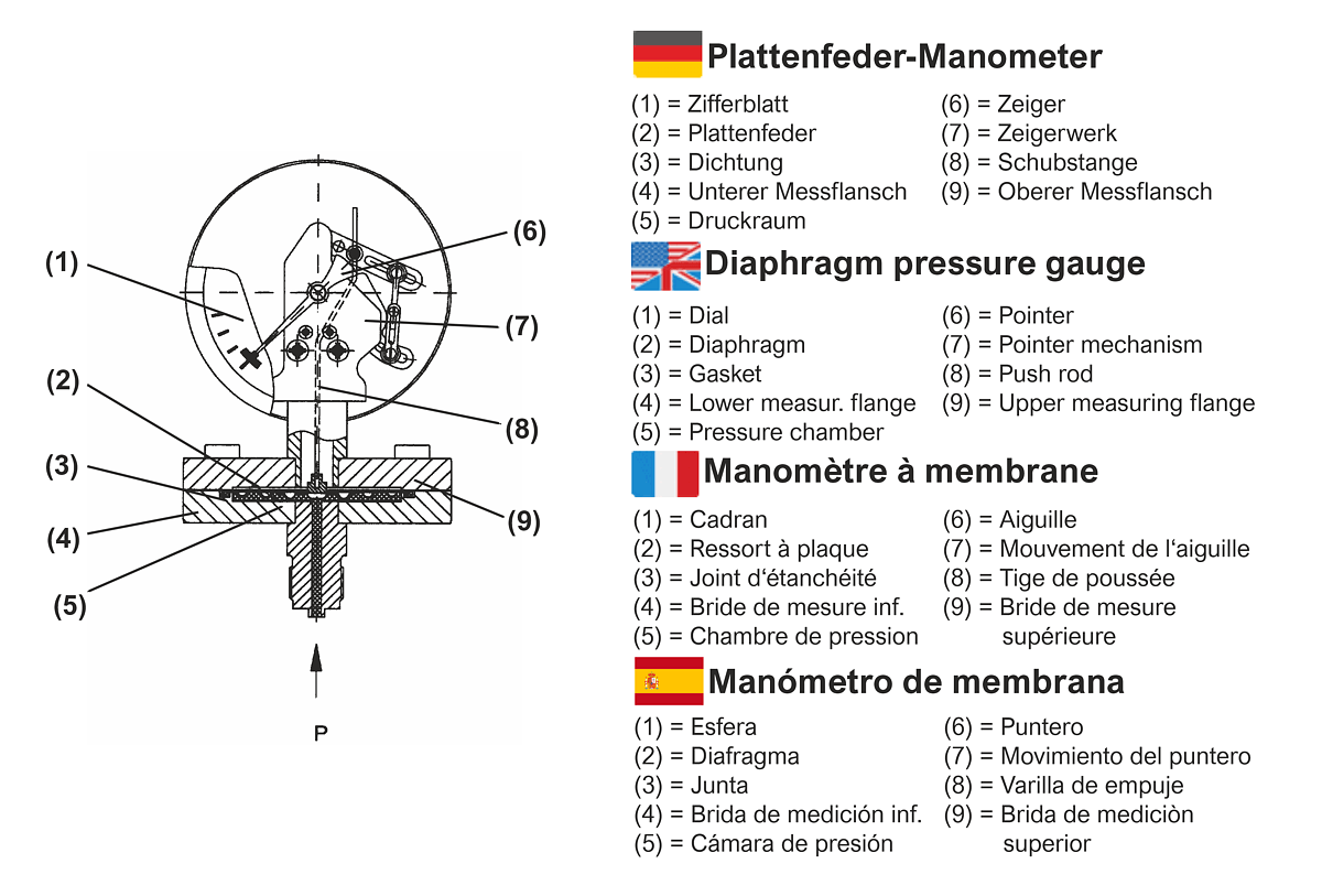
A circular diaphragm with several annular concentric corrugations, clamped between two flanges, forms the measuring element of a diaphragm pressure gauge. When pressure is applied to one side, the diaphragm bends and this deflection is the measure of the applied pressure. The spring deflection is between 1.3 and 2 mm. This spring travel is transmitted to a pointer mechanism via a push rod. The pointer mechanism converts the linear movement of the push rod into a rotary movement. This is displayed on the scale (dial) via the deflection of the gauge hand.
For design reasons and also as desired, the relative overpressure is measured with respect to the unpressurized side of the diaphragm. From a physical point of view, this measuring principle is therefore a differential pressure measurement between these two pressures. If the opposite side of the diaphragm is also pressurized, a differential pressure measurement is made.
Special features
Diaphragm pressure gauges are used for display ranges between 0...10 mbar and 0...25 bar. For pressure measurements up to 400 mbar, diaphragms with a diameter of 126.5 mm are used, clamped in measuring flanges with a diameter of 160 mm. For pressure measurements from 600 mbar, the diaphragm diameter is 75 mm, clamped in 100 mm diameter measuring flanges. Diaphragm springs for smaller pressure measuring ranges therefore have a larger pressure gauge and a larger number of corrugations to provide the necessary actuating forces for the pointer mechanism.
For special applications (aggressive media) the plate springs can be covered with special materials, e.g. PTFE, tantalum, silver or nickel.
Pointer movements
The gear ratio of the pointer mechanisms is matched to the travel of the plate springs. They are high-precision precision mechanical components that must meet a number of special requirements: they must be robust, low-wear and low-friction, and must also be able to operate independently of position. The bearing seats of the segment shafts and the pointer axes are made of nickel silver and/or brass or stainless steel and have a very good surface finish. This ensures silky-smooth running of the pointer, minimizes wear, and thus increases the service life of the device.
Housing
Housings protect all internal parts of the pressure gauge from mechanical action and contamination. The housings for diaphragm pressure gauges are made of steel or stainless steel.
Application
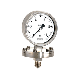
Diaphragm pressure gauges are the most robust analog pressure gauges. They are not so much sensitive to vibrations of the plant and pressure pulsations from the measured medium, because a plate spring cannot oscillate. In terms of design, they are very complex and therefore more expensive than Bourdon tube or capsule pressure gauges. Diaphragm pressure gauges are suitable for all gaseous and liquid pressure media that do not attack the material of the wetted parts. In the case of crystallizing or highly viscous media, open flanges can be used as process connections. In this case, "clogging" of the pressure gauge is largely excluded, provided that the medium does not harden (e.g. during cooling). Diaphragm springs can be protected against overpressure by filling the flanges with a special potting compound.
Display ranges: 0...10 mbar to 0...25 bar, -10...0 mbar to -1...0 bar as well as manovacuum ranges.
Housing diameter: nominal size 100 and 160.
Accuracy classes: Cl. 1.6 and Cl. 2.5.
Applications
- Mechanical and plant engineering
- Power supply
- Pump systems
- Chemical and petrochemical industry
- Water treatment
Application limits
Diaphragm pressure gauges are not available in accuracy classes Cl. 1.0 or better due to their design. Measuring ranges above 25 bar are not possible or do not make sense. The connection position of the process connection is usually only possible vertically downwards (bottom connection).